Upravit stránku

ASSEMBLY INSTRUCTIONS FV AQUA

USE OF THE SYSTEM

System FV AQUA PPR and PP-RCT enables distribution implementations in residential houses, administrative and public buildings, in industry and agriculture. It is intended for delivery of cold and hot water and also for central heating, provided that the prescribed rules are met. It is necessary to select suitable kind of pipes with corresponding parameters of limit operating temperature and pressure. The system FV AQUA offers pipes PPR, PPR-RCT HOT, PP-RCT UNI, FASER and STABIOXY.

The system can also be used for air distributions. A possibility of leading other liquids, gases or solids needs to be assessed individually in every particular example.

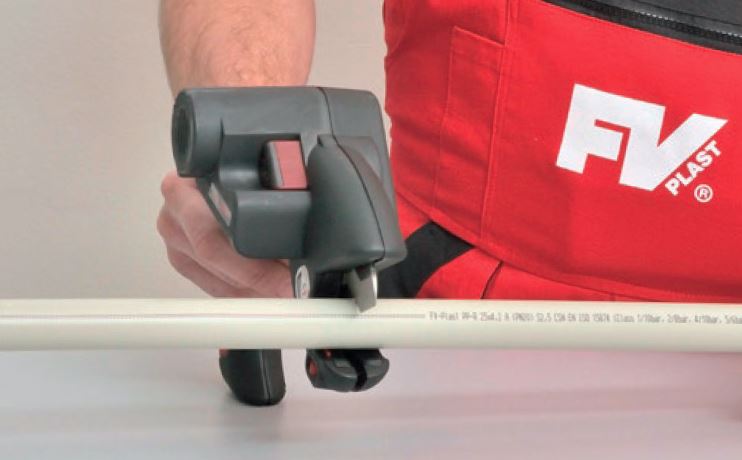
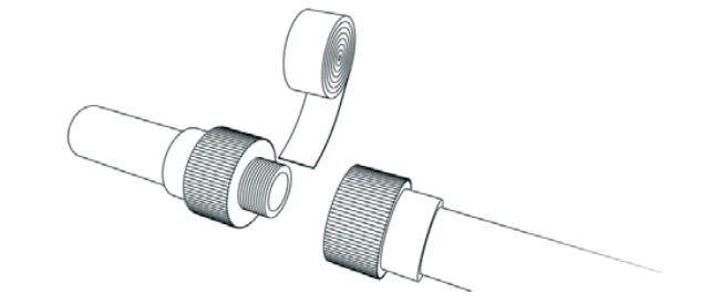
All pipes can be connected by a complete range of PPR pipe fittings by a polyfusion welding (up to the diameter of 125 mm) or by butt welding (diameters beyond 160 mm).

Water distributions

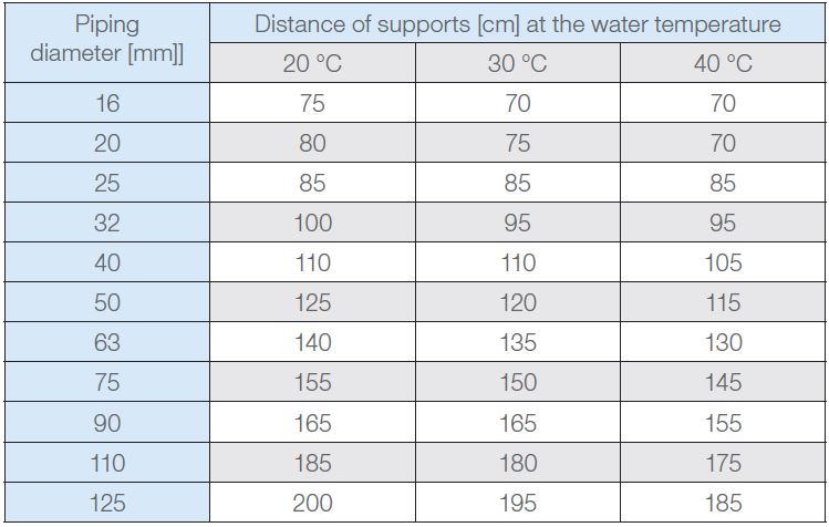
The system can be used for all inner water piping systems (cold drinking water, cold service water, hot water, circulation). An expected lifespan for a plastic piping system is 50 years providing the right material, type of a piping and correct implementation.

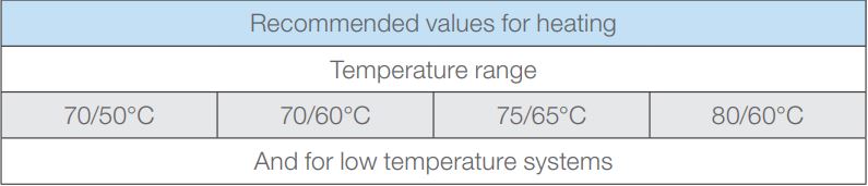
Type of a pipe according to the system of the hot water heating and its temperature regulation is selected by a project architect. In the case of hot water distribution, the expected maximum water temperature at the outflow tap is 57 °C as a protection against scalding, and inside the distributions themselves, there is a possibility of short-term water overheating to higher temperatures (70 °C) at the point of heating due to the hygiene, mainly in order to eliminate pathological organisms.

Heating distributions

When considering the suitability of a particular type of piping for heating, it is necessary to use the value of input calculating temperature of the heating water, which is the highest temperature that is reached in the system. A project architect of the heating system chooses it depending on the required temperature at the input of the heating units, according to technical possibilities of the source of heat and the type of expansion vessel.

During the installation of a plastic piping behind a boiler we recommend, with respect to protection against the system overheating, to install 1.5 m – 2.m of metal pipings behind the boiler.

Ways of leading of the pipings for water and heating distributions are identical. The basic requirements are securing of the mechanical protection of the piping and securing the support of the pipings and dilatation compensations.

Piping can be led:

  • in the grooves of walls
  • in installation dividers (prewall assembly)
  • in floors and ceilings
  • along the walls (freely or in covers)
  • in installation shafts and sewerages
  • pod omítkou
  • v sádrokartonových příčkách a podhledech

It is necessary to assess the leading of the piping outside the object according to specific conditions.

2. ASSEMBLY INSTRUCTION

2.1. Warning

During the assembly, it is only possible to use elements which were not damaged or polluted during the transport and storage. In view of welding, the minimal temperature for the assembly of plastic distributions is +5 °C. At lower temperatures, it is difficult to ensure the conditions for the formation of quality links.

Over the whole course of assembly and transport, the elements of the plastic system must be protected against impact, shocks, falling material and other ways of mechanical damage.

Bending of a pipe is carried out without preheating at the temperature +15°C minimum. For pipes of a diameter 16-32mm, the minimal bending diameter is 8 times the diameter of the piping (D).

It is unacceptable to bend a pipe with the aid of heating with an open flame or with hot air.

Crossing of pipes is carried out by elements designed specifically for this purpose.

Connecting of plastic parts is carried out by polyfusion welding, and also by welding with electro pipe fittings and butt welding. In the process of welding, a high-quality homogeneous link arises. For connecting, it is necessary to observe the strict procedures and use appropriate tools.

For threaded links, it is necessary to use pipe fittings with a thread. Cutting of threads on plastic elements is forbidden. Threads are sealed by Teflon tape, sealing thread or special sealants.

If a combined pipe fitting is followed by a metal pipe, it is not possible to connect the metal pipe in the vicinity of a pipe fitting by soldering or welding, because of possible heat transfer into the pipe fitting.

For closure of wall bends or alternatively of universal wall set before the assembly of outlet fixtures, we recommend to use plastic plugs (plastic plugs are intended only for a temporary use – e. g. pressure test). For long-term closure, plugs with a metal thread must be used.

2.2 Longitudinal expansivity and contractivity

A temperature difference during the assembly and during the operation, when a medium with a different temperature than the assembly temperature is transported through the piping, causes longitudinal differences – lengthening or shortening (l).

Δl = α · L · t [mm]

  • Δl Longitudinal change [mm]
  • α Coefficient of thermal longitudinal expansion [mm/m °C], for the all-plas  tic piping PPR design α = 0,15 | for STABIOXY and FASER α = 0,05
  • L Calculating length (distance of two neighbouring fixed points in line) [m]
  • t A temperature difference at assembly and at operation [°C]

LS = k · √ (D · Δl) [mm]

  • LS Free compensatory length
  • k Material constant, for PPR k = 20
  • D Outer diameter of piping [mm]
  • Δl Longitudinal change [mm] calculated from the previous formula

U - compensator

PB Fixed point

KU Sliding point

L Calculating length of the piping

Ls Compensatory length

Δl Longitudinal change

LK Width of the compensator

Lk = 2 · Δl + 150 [mm] and also Lk ≥ 10·D

LK Width of the compensator

Δl Longitudinal change [mm]

D Outer diameter of piping 

A suitable way of compensation: piping is deflected in the direction perpendicular to the original route and at this perpendicular, a free compensatory length (marked L) is left, which ensures that no significant additional pressure and tractional tensions arise in the wall of the piping. Compensatory length LK depends on the calculated lengthening (shortening) of the route, material and the diameter of the piping. In the case of polypropylene, for compensation of longitudinal changes flexibility of the material is used. Apart from the compensation at the bending, bending “U” compensators and loop compensators are used.

The value of the longitudinal change and the value of the compensatory length can also be read from the graphs.

Table for installation of a compensation pipe

Compensation pipe

PB Fixed point
KU Sliding point
L Calculating length of the piping

An example of a compensation by changing the route adapted to the building structure

„U“ compensator

Calculated free length L means the length without any fixed supports or suspensions, which could impede the dilatation. Free length L should not exceed the maximum distance of supports according to the piping diameter and the temperature of the medium.

Longitudinal lengthening: an all-plastic piping PPR and PP-RCT

Example: L = 8 m, t = 40 °C

Longitudinal lengthening: pipings STABIOXY and FASER

Example: L = 10 m, t = 40 °C

2.3. Distances of the piping supports

Maximum distance of the supports of all-plastic pipings FV PP-RCT UNI horizontal piping.

Maximum distance of the supports of all-plastic pipings FV PP-RCT UNI horizontal piping.

Maximum distance of the piping supports FV PPR CLASSIC S3,2 SDR7,4 (PN16) and FV PP-RCT HOT S3,2 SDR7,4 horizontal piping

Maximum distance of the piping supports FV PPR CLASSIC S2,5 SDR6 (PN 20) horizontal piping
Maximum distance of the piping supports FV PP-RCT FASER COOL horizontal piping.
Maximum distance of the piping support FV PP-RCT HOT and FV PP-RCT STABIOXY horizontal piping.
For vertical piping the maximum distance of supports is multiplied by the coefficient 1.3.

2.4 Pipe fixing

It is necessary to respect the material of distribution systems, i.e. primarily longitudinal thermal expansivity, necessity of compensations, given operational conditions (combination of pressure and temperature) and the way of connecting. Fixing of distributions is carried out so as the fixed points and sliding points are distinguished, for the expected longitudinal change of the piping.

At a pipe bend
At a branching point
At the point of placing of the fitting on the piping
Thanks to the tightly tied sleeves (only horizontal piping)
Fixing at fitting places
Free sleeve
Suitable for cold water distribution systems
In the case of hot water, sleeve is installed with insulation that is larger by one dimension.

Another way of laying of plastic piping

Laying of a pipe into a free gutter.
Leading of piping in insulation under plastering

Leading of piping

Piping has to be assembled with a decline of at least 0.5 % towards the lowest places, where it is possible to drain it through an independent draining or through
closing valves with draining. Piping must be divided into parts which can be closed independently. For closing, direct valves or cocks are used, for the instalation under plastering under- -plastering valves or cocks are used. Before the assembly of the elements, it is necessary to test their closability.For termination of the pipin g at a place of mixing outlet fixture, it is recommended to use UNIVERSAL WALL MOUNTIG GROUP, where the pitch of threads is slided under in such a way that after a potential deflection from the horizontal axis the distribution could be balanced by levels (etážek). For assemblies under gypsum, a ELBOW FOR GYPSUM WALL MOUNTING should be used. When leading a water pipe through installation partitions, it is necessary to fix the position of the pipe by suitable fixing, for example by a system of metal sleeves with supporting elements. Piping has to be led with a potential dilatation andinsulated.

When leading a water pipe in floor or ceiling constructions, bendable plastic cable ducts (from polyethylene) are used, which ensure mechanical protection of the pipe and at the same time the air gap between the pipe and the cable duct creates thermal insulation. Free plastic water piping has to be furnished with quality
insulation (if for example a cold water pipe is led freely at a wall in a heated room, there is a great danger of condensation of humidity at the walls of the pipe). Piping can be led freely at a wall only in premises without the danger of mechanical damage because of operation.

2.5 Leading of an ascending pipe

In the case of an ascending pipe, close attention has to be paid to the layout of fixed points, sliding points and to creating a suitable way of compensation. For asc ending pipes, compensation is ensured either by a sliding point at the foot ofa standpipe or by using a compensation pipe.

Assembly regulation

If a standpipe needs to be divided into several dilatation sections, this placing of fixed points is carried out. Fixed point at an ascending pipe is installed below and above a T-piece at the branch or at a coupling sleeve at a place of pipe connection, which simultaneously prevents the standpipe from falling. Dilatation between the fixed points then needs to be enabled. At a place of branching of a connecting pipe, a standpipe dilatation needs to be taken into account:

Sufficient distance of a standpipe from a wall penetration

Pipes STABI and FASER have 3x smaller expansivity and 3x higher toughness than all-plastic pipes. Therefore, the pipes can be assembled according to the same principles that were described above in the case of all-plastic pipes, that is to say in a classical procedure of a compensation solution, where a possible larger distance of supports and dilatation and compensational length will be significantlylower. When the piping is led in a groove, so called solid assembly can als o be utilized – fixed points are attached to the pipe in such a way that the thermal expansivity is transferred to the pipe material and it does not manifest. This assembly assumes sleeves which will be able to truly hold the pipe and which will be anchored firmly enough.

2.6 Connecting into a system

A piping system can be connected by welding or by mechanical links. Connecting a pipe with a pipe fitting is carried out in the same way for all types of pipes, pipe fittings are identical. Before welding, in the case of the STABI and STABIOXY pipes, it is necessary to remove the outer PPR and the middle aluminium layer using pipe shavers to the length of the insertion.

Pipes and pipe fittings are being connected by polyfusion welding, larger diameters by means of electro pipe fitting or by butt welding. All the methods have tobe carried out exactly in accordance with approved working procedures.

Dividing of pipes

Pipes can be divided (cut) only by sharply ground tools. It is recommended to use special shears or a cutter for plastic pipes.

For plastic – metal transitions in hot water and heating piping systems, plumber’s unions with impressed brass nickel-plated male and female threads are strictly used.

For tightening of threaded links with impressed threads, tightening spanners with tape are used, if the plumber’s union is not furnished with a polyhedron directly at its metal part.

WARNING:

Using of plumber’s unions with plastic threads is unacceptable for sanitary technology, because of thermal-technical and physical-mechanical reasons. Plumber’s unions with plastic threads can be used for example in the case of establishing temporary distribution systems.

Link sealing

Sealing of threaded links is carried out exclusively by Teflon tape, Teflon thread
or by a special sealant. .

This website uses cookies

This website is using cookies to provide services, personalize ads, and monitor traffic. By continuing to use this site you are agreeing with usage of cookies. More information.

Settings

Your privacy is important. You can choose from the cookie settings below. More information.